Ok, I have left this long enough. Time to get some parts off the bench and on the engine!
I maneuvred the engine onto a jack. This arrangemebt would also help later (I hope) with the installation into the car. For now it will suffice in letting me attach the flywheel, clutch and gearbox.
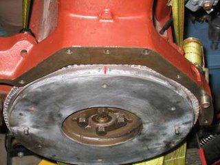 With the flywheel off the car, I took the opportunity to add a red highlight to the TOP and 1/4 marks to make them easier to see. I picked red since it is my favorite colour (the red is similar to the one used on pre-war Alfa 1750's).
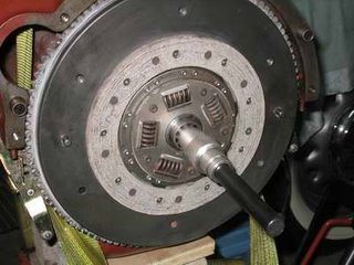
Lining up the pins on the crank, the flywheel is put in place. I add the bushing in the end of the crank (for the pin end of the gearbox shaft). The 4 bolts and their 2 securing clips are installed and tightened... tightly!
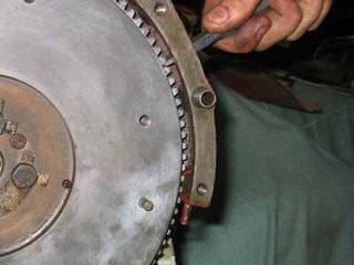 To avoid spinning the flywheel while tightening the bolts, I insterted a chisel in the viewing hole on the side of the block.
here is no use having a flywheel without the mechanism to connect it to the gearbox!
One tricky thing (for those who have never done this before) is aligning up the clutch plate with the pressure plate and the gearbox shaft. The first time I did this I used a wooden dowel wrapped up with tape! It worked... barely.
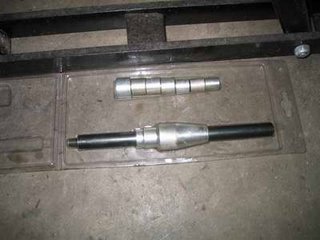 This time around I decided to use a better tool... barely. I obtained a universal clutch alignment tool. My first clue as to why it would not work as is was the key word "universal". As we have discovered, Singers are anything but universal, rather they are unique!
The idea here is to have the shaft of the tool to fit in the bushing in the back of the crankshaft. Another part of the tool then fits in the hole of the clutch plate and voila! aligned.
 This simple idea was achieved after some milling of the smallest "bushing end" piece of the alignment tool to allow it to actually fit in the bushing.
 With this done, and the clutch plate in place, the pressure plate could now be installed. Aligning pins ensure that the pressure plate is correctly oriented. Then the 6 bolts are installed. I proceeded to tighten the bolts, a few turns at a time cris-crossing as I proceeded so that the forces of the bolts would be evened out during this process.
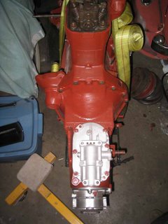 With all this in place, the gearbox was installed and slid on with ease!
My next post will show me in the hospital after throwing out my back during the engine/gearbox installation process.
The ring gear changed from the A to 4A Roadsters. The difference is the number of teeth on the ring gear as well as the on the starter gear. Keep this in mind and only use A series ring gear with A series starters.
That being said, I was in the enviable position of having TWO flywheel/ring gear. One nice flywheel had an awful ring gear. The other had a questionable flywheel and a nice ring gear. What to do... what to do... Got it! I will swap them over!
The ring gear are shrunk on the flywheel. That is that it held in place simply by the inside of the ring gear being smaller in diameter than the outside of the flywheel. How does this happen? Well to install the gear, it must be heated which allows the metal to expand and the inside diameter increases. To help matters along for installation, the flywheel can be cooled which causes the metal to shrink. Place the expanded (and hot) gear on the shrunk (and cold) flywheel and let nature/physics take their course.
The end result is a ring gear that is held tightly in place and can be replaced should it become worn.

 There is no sense in having a shiny petrol pump and carburetor without something to link the two together! How about a nice copper tube? Yes you say, well let's get to it!
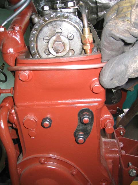
The engine that I am rebuilding came with a perfectly good petrol pipe. It also came with an unknown Solex carb. The pipe was definitely made to fit the carb option. My setup features a SU Down draft (see Part 12) so there were a few issues to deal with. First was that the pipe was a bit too short, the other was the carb connector. I wanted to use the banjo connector that was originally with this carb. I think that they are cool, and for that reason I will take the hours and hours to painfully reconstruct a new pipe. Actually it too less than 20 minutes from start to finish, but do not tell anyone.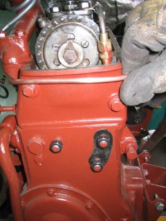 I started by straightening a piece of coiled copper pipe. Copper is great because it is able to take a bend rather easily. This also means that care must be exercised so as not to kink the pipe.. Being the ever nit picker, I evened out the bumps by rolling it on the floor of the garage under a piece of ply. If you have ever made snakes out of clay as a kid, you see what I did. No measuring yet, but I did make sure that the pipe was definitely long enough.Then I made the fitting for the pump-end of the pipe and attached it to the petrol pump. From there I gently bent and curved the pipe to follow the ins and outs as well as the ups and downs and the spins to follow the curves of the engine. I used the original pipe as a guide especially to see where the pipe passed under the lower water manifold and around the breather tube.
 During much of this process it was necessary to remove the pipe, make a bend reinstall the pipe, and so on Do not forget to add the clip for the front of the pipe. The clip secures the pipe in place by using one of the bolts that secure the front head cover. This is a crucial part since we would not want our smart looking petrol pipe to bang into the whirling fan.
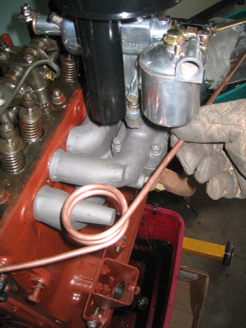
 The original pipe featured a single loop on the carburetor side of the engine. I wanted to add an extra loop based on a few photos of other cars of that era. Weather it is right or wrong, the difference will not be felt by the system. I also paid extra attention to the distance that the petrol line comes to the exhaust manifold as this is the area where the loop would be. Perhaps the Singer designers thought that this would pre-heat the petrol.
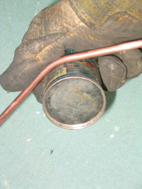
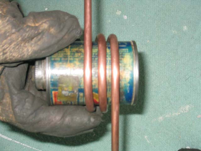
 Making the loops was a snap... with the right tools (in this case a can of anti-seizing compound). I wrapped the pipe around the can (twice) and simply removed the can. The result is quite nice.Then another bend to bring the pipe up to the carb. With the banjo in place, the bend was made and then the pipe measured for cutting.Again a fitting session with the banjo in place and the pipe inserted. Any final adjustments can be made to the length of the pipe.
 Once everything is as we want it to be, I mark the pipe and banjo so that they can be aligned properly when joined permanently. A quick soldering job (another nice thing about using copper) and we are done!A pass or two with some steel wool was just the trick to make it look nice.Getting closer!
Work continues, but the "to do" list is getting shorter!This time around I tackle the manifold and carb. The manifold is easy: Put the two pieces together and paint them. Well, it is not that easy. There was no need to separate the intake manifold from its partner the exhaust, but wanting to clean everything up, I did. The tricky thing is, that these two parts must be flush at the end where they meet the head, so if in doubt have them shaved so that they doi. I had this done at the same time as the head and block. Do remember to add the little tab for the accelerator retraction spring, you do not want to remember this after everything had been painted. Speaking of painting, I go back to using the Por 15 High Temperature Coating. Manifold grey will do nicely here. I took the opportunity to paint the studs, nuts and the fancy "wings" (manifold bridge according to the parts book). The paint goes on pretty goopy. Having used it about 5+ years ago I had forgotten how it performed... or the paint had gone bad. Lucky for me, it was the former and it dried with smooth surface. Well, as smooth as a cast iron piece can be.What a nice way to top a manifold than with a carburetor! The down draft SU does turn a few heads. At the Hudson British Car Day I overheard a few fellows discussing the Roadster's carburetor. From what they were saying, they thought that this was a modification and would probably not work. Tsk tsk tsk. Unfortunately I did not have the chance to educate them on the finer points of this British design.I received a beautiful carb from Mr. Len Percey. He had gone to the trouble to get it prepped for me by blasting it with walnut shells and did a great job. Too bad it was the wrong size. As I prepared the carb for installation, I realised that although it looked like the right one, it did have some important differences. The flange to mount the carburetor to the manifold was 90 degrees from where it needed to be. Plus it was a full 1.5 inches taller and the throat was bigger. This would have led to a few fit problems with the air cleaner and possibly an interference isue with the bonnet.
 What to do. What to do. The donor carb was in excelent shape, bigger, but excellent. Now, when I bought my Roadster in 1999, it included a myriad of bits and pieces. There were a few boxes, one contained a half full box of miscellaneous nails - rusted together. There were some carburetor parts, but since there was a complete carb on the engine, I paid it no mind, in fact I had forgotten about it! This was until I was until I was going through my parts bins looking for shocks for the Super Ten.
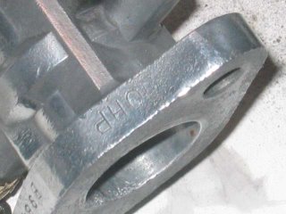 What I found was a fairly complete down draft carb. Lucky for me, the parts that it was missing were ones that I could transfer from the other! I needed to make a few modifications to the accelerator lever so that it could double as an attachment point for the spring, but that was a snap! Once I knew that I had everything I needed, I thought that it would be nice to polish up some of the bits. LAter I found a stamp on the mounting flange. Hard to read I made out "10HP". This had to have been the original carb for the 10 HP engine that is currently in the Roadster! More luck!
 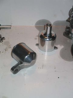 With everything to be polished polished, and the other bits cleaned up, I was ready to reassemble the carb. The trickyest part of all of this is ensuring that the needle is aligned properly with the hole in the shaft that is controled by the choke knob. Should these not be aligned then the needle will bind, or not seat completely creating a whole slew of problems.
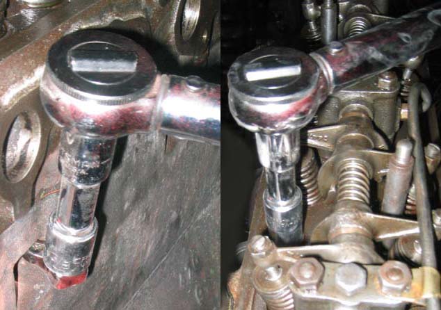
 I inserted the needle into the hole in the piston. The shoulders of the needle should line up flush with the face of the piston. With this done, I assembled the rest of the "bell" and attached it to the body of the carb. Be careful not to bend the needle, a bent one works worse than one that is not aligned.
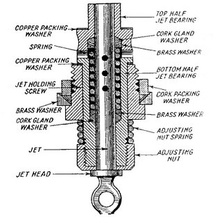 Assemble the cork gland washers that form the jet portion of the carb. The way that the jet assembly works is that petrol from the carburetor bowl flows into the jet. The flow is controled by the needle which is controled by the piston which is controled by the vacuum produced by the engine which is controled by the butterfly valve which is attached to the accelerator peddle. The further back the needle is the more petrol flows. This is also how the choke mechanism works, by pulling the jet away from the needle, even more petrol is sent to the engine. The small cork gland washers ensure that the petrol flows only through the jet. If you noticed the old seals that you took out of the carb as you may have seen the two oblong washers. They are trapped by each and of the chamber and again by a dished brass washer held in tension by a spring. Hold the internal jet parts in by lightly screwing in the jet holding screw and large brass (or alloy) washer and cork packing washer. We have not aligned the jet yet, so do not tighten it too much. Now we add the spring and jet adjusting nut at the end of the jet. The jet adjusting nut controls the distance that the jet is from the needle in its normal position anf thereby the mixture. For an initial setting, you first turn the jet adjusting nut until it stops. Then back off seven flats (a turn and a flat).
 Insert the jet into the assembly and then tighten jet holding screw. Once the jet assembly is in place the pressure on the washers to the cork gaskets makes them swell around the shaft of the jet. It is for this reason that we use a rebuild kit whenever we dismantle the jet. Check that the piston (and needle) operate smoothly and if it does not, then slacken off the jet screw and try again.
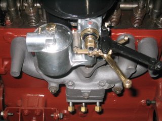
Assemble the rest of the carb by adding the choke cable holder and arm, the spring, and in my case the throttle advance.
Looks good, but the proof will have to come later.
By the way, to adjust the carburetor to the right fuel/air mixture you follow this procedure:
- Get the engine to its normal working temperature.
- with the engine idling at approximately 1500 RPM (higher than usual), move the piston 1/16 of an inch using a wire or small screw driver.
If the engine speeds up then the mixture is too rich and you should tighten up the jet adjusting nut.
If the engine quits then the mixture is too lean and you should loosten the jet adjusting nut.
If the engine continues to run but struggles then it is ok.
When making adjustments, turn the jet adjusting nut a flat at a time.
Singer made things very east for the enthusiast who wanted to adjust their valve timing to suit just about every need. Me, I just want the engine to be back to the was it likely left the factory. Anyone who has had the head off their car, and removed the cam gear may have noticed that the six holes are not symmetrical. This is where you (as the Singer tweeker) can adjust the valve timing to your hearts content. I will show you an easy method to get things back to where they were when your engine was first put together.
First, the head must be in place and tightened down. We do not want a fraction of a millimeter interfering with our precise measurements!! After all, I am sure that when these engines were first assembled there were teams of engineers with micrometers adjusting everything to ensure precise installation. Or, there was a method that the skilled worker with a minimum of tools could set up everything simply and accurately.
There is one method which I have come to know as the "Smiley Method". This was shown to me by Bill Haverly during his visit to my garage some years ago. Since I shared this little gem in an article I wrote it has created some debate over who first discovered this trick. Especially since I would figure that it was someone at the Singer factory. I let those who have more time, energy and/or sense, debate its origin. I am content in knowing that it works and has helped me, and many others out there, get their cars up and running. On a side note, one of the factors in my acquiring my Roadster in 1999 was that the previous owner could not get the engine to work. I was as oblivious as he as to why (so I did not take advantage of this fellow) but now can see how this situation could and did arise.
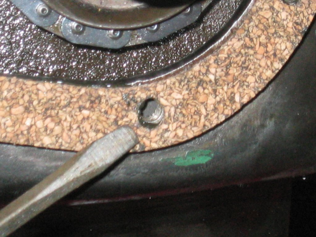
With the head now in place, I install the chain tentioning gear. I find it easier to do this now before the chain and cam gear are installed. This assembly will interfere with the valve timing process so once everything is attached, I use a wire to pull it away from the area and keep it in that position by securing the wire to a stud or bolt through the breather hole and onto a stud or bolt.
The timing chain will ultimately drop into its channel at the front of the engine. A coathook (or similar device) can be used to fish for it. Should this occur DO make sure that the chain is around the gear on the lower gear on the intermediate timing shaft.
SMILEY FACE METHOD
WARNING - This will likely require a lot of fiddling around with the cam gear, chain, crank, etc.
1) Find Top Dead Center (TDC) for the crank.
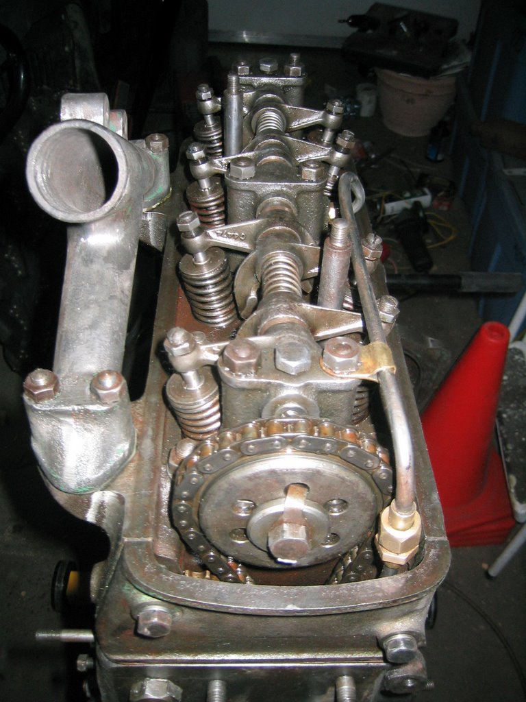
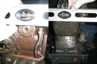
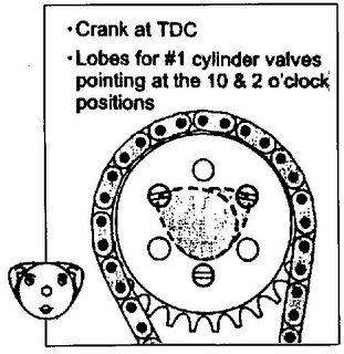 2) Rotate the cam until the lobes for cylinder one are pointing up at the 10 & 2 o'clock positions. The three studs at the front of the cam should be arranged with the top two parallel to the face of the block/head. With the engine on a stand, I adjusted it until it was level, then I could use a level resting on these studs to ensure that the cam was indeed in the proper position.
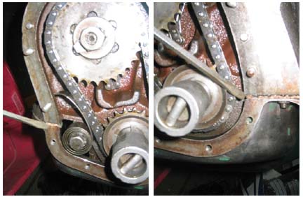
 3) Slip the cam gear into its chain and while ensuring that there is no slack on the "exhaust manifold side", attempt to find which of the hole pattern fits in the studs WITHOUT rotating either the crank or the cam. If you get it perfect on your first try, proceed immediately to your nearest lottery outlet and buy one ticket for the biggest prize. With your luck, you only need one. If you are like me, then you will need to adjust the cam gear by rotating it, replacing it in the chain, trying again, rotating it, replacing it in the chain, trying again, rotating it, replacing it in the chain, trying again until at last you get that satisfying click as it glides in place.
4) Put in the washer, lock washer and bolt to secure the gear. I do not tighten it up fully at this point, because I want to test it all before I commit to tightening it all up.
I turn the crank a time or two, ensuring that I get it back to TDC. Then I inspect the "eyes" and "ears" of the cam and if all checks out, I tighten away. If not, then it is back to step 3. Better safe than sorry.
5) Once you are satisfied with the alignment, the chain tenionning gear can now be released from the wire holding it back.
 6) You can now see how close the oil feed pipe from the block is to the timing chain and gear! Secure the pipe in place and ensure that it does not touch any moving part (duh). We can also install the continuation of the oil feed pipe for the head. I attach it to the center cam bearing first, leaving enough slack in the nut to let me move the pipe if necessary. Then to the union joint for the newly secured feed tube from the block. A final tightening of the nut at the center cam bearing and attaching the clip
 to the forward stud and voila!
Your timing should now be set up for starting... which we will not do until the other parts are installed and the engine is in place.
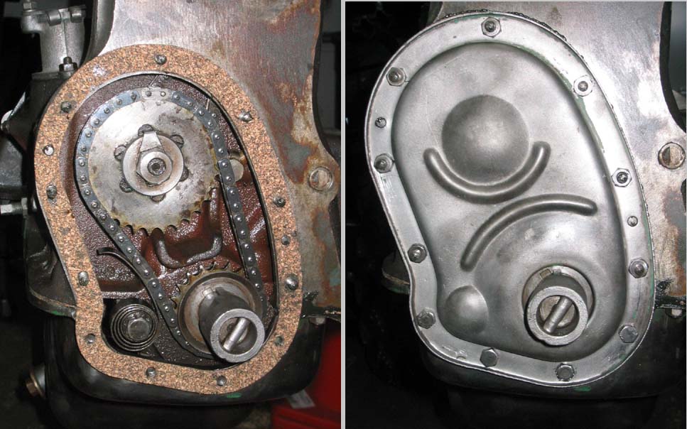
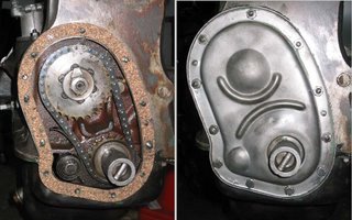
Speaking of which, lets install the timing gear cover plate and the upper water manifold.
What is next, well that is a horse of a different colour!
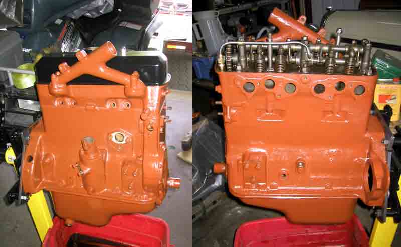
 With things rapidly moving ahead, the next item on the menu is the head. Singer was a leader in the introduction of the overhead cam shaft. This arrangement provides a more direct link between the cam and the valves they control. Great for simplicity! Well you would think so, more on that later.
 Now that the head and ports cleaned I proceeded to install the valves. A borrowed valve spring compressor came in handy (thanks Phil). One by one the valves were inserted and the collets put in place to secure them. Now I was ready to install the cam. Again, notes and/or photos of this area before dismantling will come in handy as the camshaft bearings are sided. The rear one is the tough one as each side is almost the same. The middle bearing has a port on the left side for the oil feed pipe and the forward bearing
 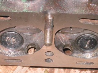 has an extension that points towards the front of the head. Once again, our slippery friend oil is used liberally in the bearings prior to installation. Tighten down the three pair of nuts that secure the cam bearings. I leave off the oil feed pipe for now. It interferes when tightening the head nuts. Speaking of these, this is a good time to install the two short studs on the bottom of the head, they are the tricky ones to deal with when torquing everything down.
Install the head gasket. Before putting it in place, I wipe it down with a lightly oiled rag.Now we can "drop" the head in place. Drop gently I mean. Care again is taken to ensure that the head gasket is not pinched and that the head settles evenly. Now we can put on the washers on the studs and screw on the head nuts finger tight for now. Remember again the two studs hiding under the manifold.
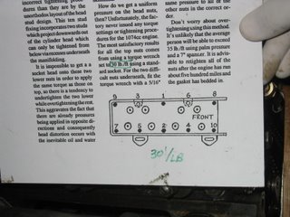
 Now we tighten. I followed the torque settings that I used from the Bill Haverly article. Also important is the sequence for tightening the nuts. The head must settle down evenly so as not to introduce any twisting which will lead to gaps between the head and block, which leads to water mixing with oil, or in the cylinder, or worse (is there anything worse?)
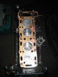
 I used a crowfoot on a short extension for the hidden nuts. There are difficult to access AND since I am tightening them from above, I had to remember to switch the torque wrench to loosen.I tightened down the head in two stages. 20 foot pounds for the first pass, 30 for the final one. Each time following the tightening pattern as outlined in the article.
 There is still the oil feed pipe from the block and its continuation to the center cam bearing. I would leave them for now, at least until the cam timing procedure has been completed... timing
... timing ...
... timing ...
Timing is everything... and that is for the next chapter.
 Just a little off the top... er bottom of the head.I wanted to try to do a good job with this engine. After all, it would be the temporary transplant for the Super Ten and the future Roadster powerplant. In keeping with this vision, I had sent out the block, head and manifold for cleaning and "a close shave" (Wallace & Grommet...get it?)Whenever sending out the head for a neat trim be sure to attach the front cover! This way, everything is at the same level. Think of it, if the head is trimmed and the cover is not, then there will be a difference in a surface somewhere - either for the head-block or head-valve cover joints.Even with the head back from the shop, there was still some cleaning up work to do. With caustic bath shops harder to find out here (some environmental mumbo-jumbo), I had the shop who carried out the trimming take care of the cleaning as well. They did do a good job, but a little extra elbow grease was necessary. Plus, it is much easier to do this now than once valves and stuff ate added.I inspected the water channels for any signs of blockages. None to report! I used a die grinder in my airtool to clean up the edges of the water channels as well as clean out the channels for the intake and exhaust. A lot of yucky carbon crud here. Thinking ahead, I wore a mask so that none of it would find its way in me! I found this kind of work to be a nice tonic with the result being a very clean head.
 The next step was to grind in the valves. I did this myself and is not difficult to do. The valves even have a slot that allows you to use a slotted screwdriver to make the job easier!When disassembling the engine, I did note which piston belonged to which cylinder. Same went for the valves. No need to label the inlet vs exhaust valves... they are different diameters! The inlet valves are larger then the exhaust ones.
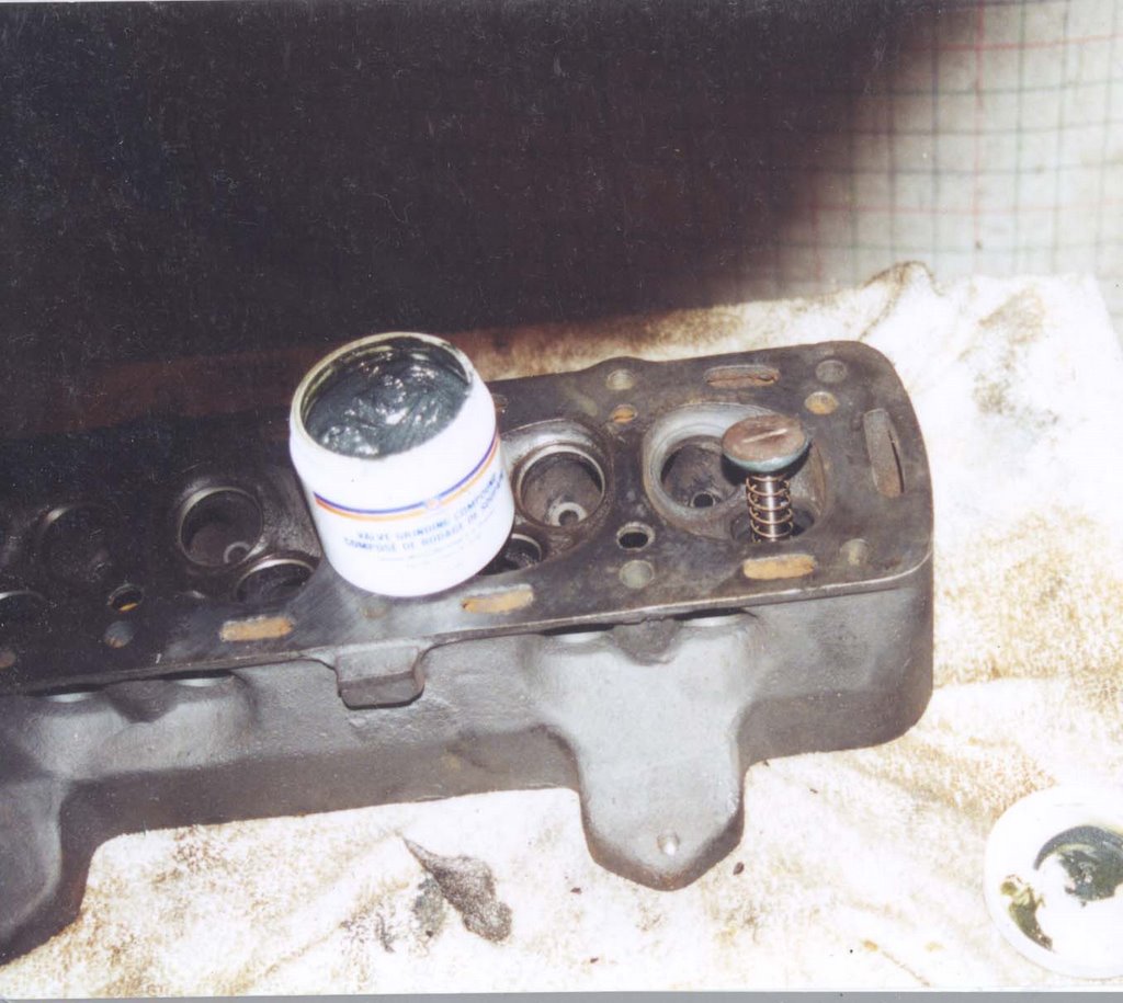
 A check too of the valve stems (for signs of being bent) and the guides (for too loose a fit) should be done.Please do not use a drill to make the job easier. The grinding procedure is to make a 360 degree turn in one direction, then a 360 turn in the other. Think of how the cowboys and indians made fire with a stick in their hands. Rubbing them to spin the stick back and forth. Same here.Prior to insterting the valve into the guide, I smeared some valve grinding compound around the edge of the valve. I also inserted a spring on the valve stem. This is handy since after some back and forth spinning, the compound is squeezed from the valve seat. Allowing the valve to rise up provides an opportunity for some of the compound to settle back where it is needed or more compound can be added.Once all the valves were ground, I cleaned everything with some thinner, basically to get all the grit out. I replaced the valves, ensured that they were seated correctly, and with the head on its back filled the "bowl" in the head with thinner. I wanted to see if any thinner could get through the seal (between the valve and the seat) into the intake or exhaust channels in the head. Any leakage would be a sign that more grinding is necessary.In my case, this was not the case, so the valves and springs could be installed.More on this later...
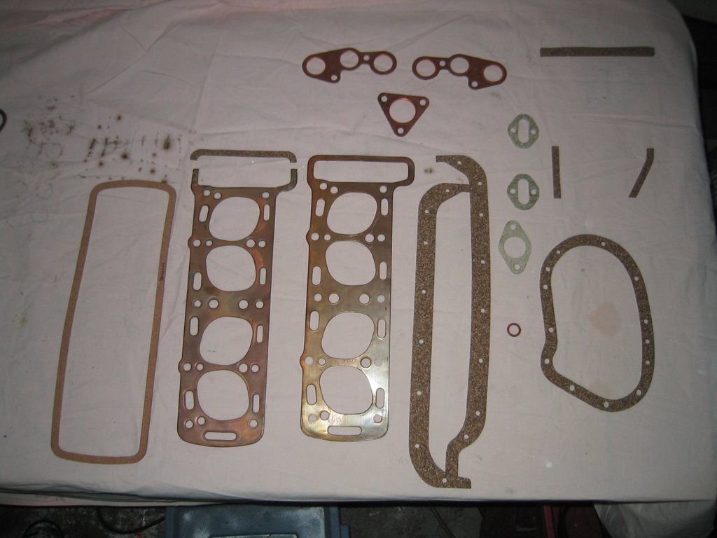
 Pile 'o Gaskets
There would be no point in reusing the old gaskets in a rebuild! So a trip to the local Heverly Singer Emporium was necessary to equip myself with a complete decarbonizing set of gaskets. This would set me up with gaskets for the valve cover, head (copper), timing gear cover (left and right), water manifolds (upper and lower), exhaust and down pipe (copper), timing chain cover and the three needed for the sump pan.
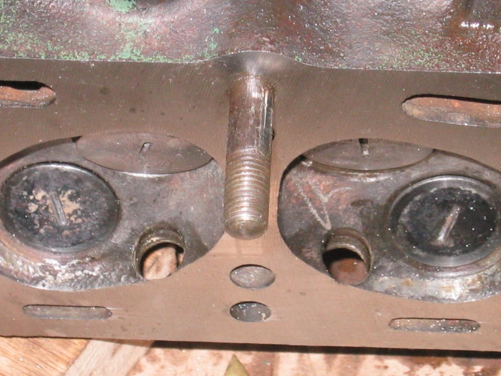
There are two types of head gaskets available. One is the original type (to the right in the photo) with a complete copper "circle" around the timing chain tunnel. The later model (to the left) does not extend completely around the timing chain tunnel but provides a cork/rubber gasket to complete the seal. In either case, a lot of attention needs to be given to this area as it has proven, to me anyhow, to be one prone to oil leakage.
 I started with the sump pan gaskets. They are split between left and right with a thick "block" of gasket material for the rear bearing. I apply a thin layer of gasket cement. I use the kind that remains flexible. The trickiest part here is in the gasket for the rear bearing. I bit more gasket cement on the bearing housing itself AND at each end of the gasket. The gasket should form around the housing and the ends meet up with the gaskets that follow the bottom of the block. Even so, a little extra goop to ensure a better seal is worth it in my opinion. Eventually you will be able to get the sump on. After it has had a chance to settle, I will come back later and clean everything off.
 Tightening the nuts here is a delicate affair. Just enough pressure, but not too much. Because of this "flexibility" in the final height of the sump, the lower four holes in the timing chain cover gasket are oval. Smart thinking Mr. Singer Engine Gasket Designer Person! If you bought your gaskets, you may have to trim the tab on the forward right side gasket that protrudes from the front of the partially assembled block.
 Another potential oil seepage location is the point where the sump gaskets meet the timing cover gasket. If the sump gaskets do not come flush with the face of the block then an extra bit of gasket goop will be necessary. Again, a thin bead of gasket cement and sufficient tightening of the cover nuts and bolts and this part is done!
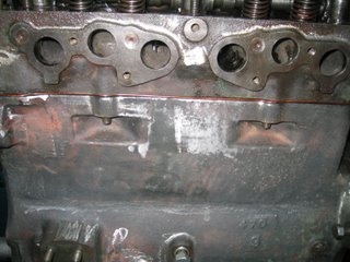
 All that is left to do for now are the gaskets for the upper and lower water manifolds. These gaskets are normally of a solid gasket material so a bit more torque can be applied.
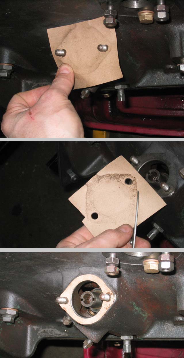
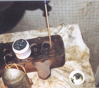
I had to make a couple of gaskets for my engine rebuild project: oil line from the pump to the block, petrol pump and the distributor housing. Making these and other gaskets is easy.
 First I cut a piece of gasket material in the rough shape of what I will need. Then, placing the material over the area I want the gasket for, I rub the edges of the facing (metal part to be "gasketed") to leave an impression on the gasket material. I cut out the necessary areas, punch out holes if necessary and voila! There are times when I will punch out stud holes before rubbing. This is used when the studs can not be removed, or they are impractical to remove. In the example pictured here, I chose to punch the holes first.
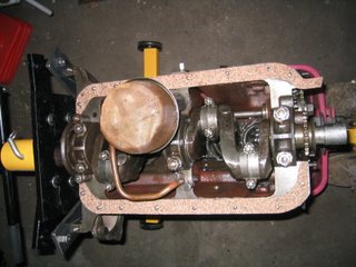
Before I install the distributor housing, make sure that you put in the distributor-oil pump-petrol pump drive shaft. With all the things that this little baby does you better NOT forget it!! When installing this drive shaft, you will have to play with it to A) line up the oil pump drive so that B) the offset slot in the distributor drive end is furthest away from the block.
WOW
To do this seemingly impossible task, I first dropped in the drive shaft in place (gently of course) so that the distributor end was roughly in the right position. Then using the starting handle, I turned the crank until the drive shaft found its mark with the oil pump. This causes the drive shaft to drop to its normal level. I then turn the crank shaft until the cam shaft is back to its initial position (Smiley Face). Check and make necessary adjustments to the drive shaft (turning the crank if necessary).
The next gasket to install is the copper/asbestos head gasket. That will have to wait for me to install the valves! (Hint - Part 8? perhaps?)
 With the flywheel off the car, I took the opportunity to add a red highlight to the TOP and 1/4 marks to make them easier to see. I picked red since it is my favorite colour (the red is similar to the one used on pre-war Alfa 1750's).
 To avoid spinning the flywheel while tightening the bolts, I insterted a chisel in the viewing hole on the side of the block.
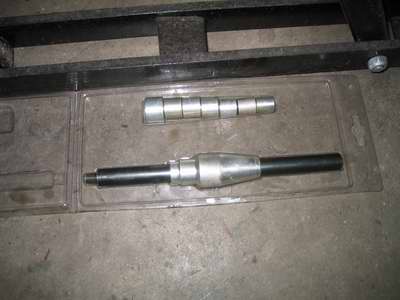 This time around I decided to use a better tool... barely. I obtained a universal clutch alignment tool. My first clue as to why it would not work as is was the key word "universal". As we have discovered, Singers are anything but universal, rather they are unique!
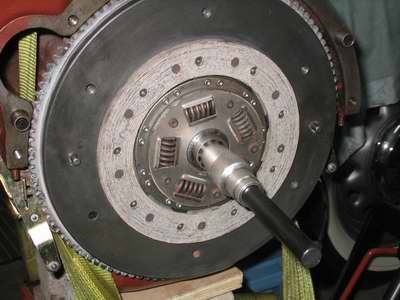 This simple idea was achieved after some milling of the smallest "bushing end" piece of the alignment tool to allow it to actually fit in the bushing.
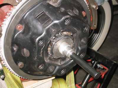 With this done, and the clutch plate in place, the pressure plate could now be installed. Aligning pins ensure that the pressure plate is correctly oriented. Then the 6 bolts are installed. I proceeded to tighten the bolts, a few turns at a time cris-crossing as I proceeded so that the forces of the bolts would be evened out during this process.
 With all this in place, the gearbox was installed and slid on with ease!